When it comes to modern electronics, everything from your smartphone to the car you drive has one common enemy: electromagnetic interference (EMI). This pesky phenomenon can cause your devices to malfunction or, worse, fail entirely. Enter the hero of our story—the EMI EMC filter.
Designing an EMI EMC filter might sound like a task reserved for electrical engineering wizards, but with the right approach, anyone can grasp the basics. Before diving into the technicalities, let’s explore why EMI EMC filters are crucial, not just for your gadgets but also for ensuring regulatory compliance. After all, no one wants their shiny new invention pulled from the market because it’s turning nearby televisions into static-producing nightmares!

To design an effective EMI EMC filter, it’s crucial to first understand the two key players in this game: Electromagnetic Interference (EMI) and Electromagnetic Compatibility (EMC). Think of them as the problem and the solution, respectively.
What is EMI (Electromagnetic Interference)?
Electromagnetic interference, or EMI, is essentially unwanted noise or disturbance in an electrical system caused by electromagnetic waves. Picture this: You’re enjoying a movie, but every time your neighbor turns on their hairdryer, your TV screen goes haywire. That’s EMI in action. It’s the electronic world’s version of a screaming toddler on a peaceful flight.
Types of EMI
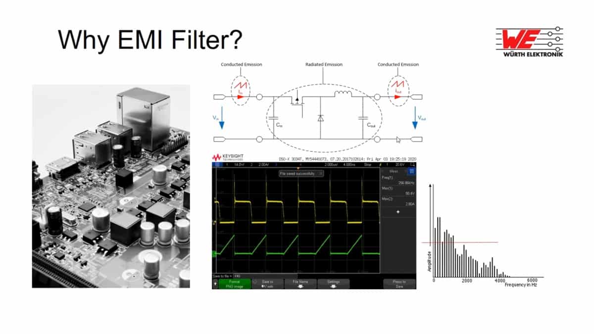
EMI can be classified into three main categories based on how it propagates:
- Conducted EMI: Travels through electrical conductors like wires and cables. For example, a poorly shielded power supply might introduce noise into your system through the power lines.
- Radiated EMI: Spreads through the air as electromagnetic waves. Think of interference from radio transmissions or unshielded electronics.
- Transient EMI: Short bursts of noise caused by events like lightning strikes, power surges, or switching transients in circuits.
Common Sources of EMI
- Switching Power Supplies: These efficient little devices are notorious for generating high-frequency noise.
- Electric Motors: Found in everything from fans to industrial machinery, motors can be a hotbed for EMI.
- Wireless Devices: Anything that communicates wirelessly—Wi-Fi routers, Bluetooth gadgets, or even walkie-talkies—can emit EMI.
What is EMC (Electromagnetic Compatibility)?
If EMI is the problem, Electromagnetic Compatibility (EMC) is the solution. EMC ensures that devices can operate in their intended environment without causing or being affected by EMI. It’s like good manners for electronics—play nice with your neighbors, and they’ll play nice with you.
Goals of EMC
- Immunity: The ability of a device to resist interference from external sources.
- Emission Control: Reducing the noise a device emits into its environment.
- Compliance: Meeting industry standards to ensure that products are safe and reliable.
Regulatory Standards for EMC
Designing EMI EMC filters isn’t just good practice—it’s often legally required. Some key standards include:
- CISPR (International Special Committee on Radio Interference): Sets limits on conducted and radiated emissions.
- FCC Part 15 (USA): Regulates emissions from electronic devices.
- IEC 61000 Series: Covers EMC immunity and emissions for a wide range of devices.
Fun fact: Products that don’t pass EMC tests are often labeled as “noisy,” which is basically the electronics world’s way of throwing shade.
Making EMI and EMC Relatable
To better understand the relationship between EMI and EMC, imagine a noisy party. EMI is the loud chatter that drowns out your conversation, and EMC is the soundproofing or noise-canceling headphones that let you enjoy your evening in peace. EMI EMC filters are your electronic devices’ noise-canceling headphones—they help reduce the chatter and let the signals flow as intended.

Principles of EMI EMC Filter Design
Now that we understand the concepts of EMI and EMC, let’s dive into the principles that guide the design of an EMI EMC filter. At its core, an EMI EMC filter is a circuit designed to suppress unwanted noise while allowing the desired signals to pass through. Designing such a filter requires a blend of theory, creativity, and practical know-how.
Key Functions of an EMI EMC Filter
The primary job of an EMI EMC filter is to keep the peace in an electronic system, much like a referee in a heated sports match. Here’s how it achieves that:
- Suppressing EMI Noise: Filters block high-frequency noise, ensuring that interference doesn’t disrupt system performance.
- Ensuring System Compatibility: By reducing emissions and enhancing immunity, filters allow multiple devices to coexist without stepping on each other’s toes.
- Enhancing Reliability: Proper filtering reduces the risk of malfunction, extending the life of your equipment.
Think of EMI EMC filters as the unsung heroes behind the smooth operation of your electronics—they quietly do their job, ensuring everything works as intended.
Types of EMI EMC Filters
Choosing the right type of filter is like picking the right tool for a job. Each filter type has unique characteristics suited to specific applications:
- Low-Pass Filters:
- Purpose: Allow low-frequency signals to pass while attenuating higher frequencies.
- Common Use: Power supplies to block high-frequency noise from AC lines.
- High-Pass Filters:
- Purpose: Block low-frequency noise while allowing higher frequencies to pass.
- Common Use: Audio systems to eliminate low-frequency hums.
- Band-Pass Filters:
- Purpose: Pass signals within a specific frequency range and block those outside it.
- Common Use: Wireless communication to isolate desired signal frequencies.
- Common-Mode Filters:
- Purpose: Suppress noise that appears equally on all conductors.
- Common Use: USB lines, HDMI cables, and Ethernet connections.
- Differential-Mode Filters:
- Purpose: Filter out noise that appears as a difference between two conductors.
- Common Use: AC power lines to reduce interference between live and neutral wires.
Basic Components of EMI EMC Filters
At the heart of every EMI EMC filter are components that work together to tackle noise effectively. Here’s a breakdown of the key players:
1. Inductors and Chokes
- Role: Resist changes in current, making them effective for blocking high-frequency noise.
- Fun Fact: Inductors work like tiny traffic cops, slowing down unwanted high-frequency “cars” on the electronic highway.
2. Capacitors
- Role: Block DC currents while allowing AC signals to pass, effectively filtering high-frequency noise.
- Types: X-capacitors (between live and neutral) and Y-capacitors (between live/neutral and ground).
3. Resistors
- Role: Dampen resonance and stabilize the circuit.
- Use Case: Often paired with capacitors to prevent oscillations in the filter circuit.
4. Ferrite Beads and Shielding Materials
- Role: Absorb high-frequency noise and reduce emissions.
- Fun Fact: Ferrites are the ninjas of the filter world—they silently eliminate noise without adding much size or cost.
Tables of Common Components and Their Applications
| Component | Primary Function | Typical Application |
|---|---|---|
| Inductor/Choke | Blocks high-frequency noise | Power supplies, motor controllers |
| Capacitor (X/Y) | Attenuates high-frequency noise | AC line filtering, PCB layouts |
| Resistor | Damps resonance | RC circuits, filter tuning |
| Ferrite Beads | Absorbs RF interference | USB ports, HDMI, Ethernet |
Why These Components Matter
These components don’t just work independently—they complement each other. For instance, pairing an inductor with a capacitor forms an LC filter, one of the most common configurations for EMI suppression. A capacitor might not be enough to block all frequencies, but when combined with an inductor, it creates a tag team that takes down even the most stubborn noise.
Steps to Design an EMI EMC Filter
Designing an EMI EMC filter may sound like a daunting process, but by breaking it into logical steps, it becomes a systematic and rewarding task. Let’s explore the step-by-step process, complete with tips, calculations, and practical insights.
Step 1 – Define System Requirements
The first step in designing an EMI EMC filter is to clearly define the system’s requirements. This ensures you’re building a filter tailored to the specific needs of your application.
Key Questions to Address:
- What are the noise sources?
Identify whether the EMI is conducted or radiated, its frequency range, and whether it’s common-mode or differential-mode noise. - What is the desired level of noise suppression?
Determine the attenuation required to meet regulatory standards, like FCC Part 15 or CISPR limits. - What are the physical constraints?
Consider the size, weight, and cost restrictions of your design. For instance, compact consumer devices may require miniaturized components.
Pro Tip:
If you’re unsure about the noise characteristics, use an oscilloscope or a spectrum analyzer to visualize the frequency spectrum of the interference. These tools provide invaluable insights into the EMI you’re dealing with.
Step 2 – Select the Filter Type
Choosing the right type of filter is critical to achieving optimal performance. This decision is guided by the noise characteristics identified in Step 1.
Filter Selection Guidelines:
- For low-frequency noise, consider a low-pass filter.
- For high-frequency noise, high-pass or band-pass filters are ideal.
- To suppress noise on multiple conductors, use a common-mode filter.
Example Scenario:
If your device emits noise at 150 kHz that needs suppression to pass CISPR 25 standards, a low-pass filter with a cutoff frequency slightly below 150 kHz would be a good choice.
Pro Tip:
When in doubt, start with a simple LC or RC filter and iterate based on testing results.
Step 3 – Component Selection
Now that you’ve identified the filter type, it’s time to select the components. This involves calculations and careful consideration of material properties.
Inductor Selection:
- Calculate inductance using the formula: L=Z2πfL = \frac{Z}{2 \pi f} Where ZZ is the impedance at the desired cutoff frequency ff.
- Choose an inductor with a high saturation current to handle peak loads without distortion.
Capacitor Selection:
- For low-pass filters, calculate capacitance with: C=12πfZC = \frac{1}{2 \pi f Z} Where ff is the cutoff frequency and ZZ is the impedance.
- Use X-capacitors for line-to-line filtering and Y-capacitors for line-to-ground filtering.
Other Considerations:
- Ensure components can handle the system’s voltage and current.
- Select materials with high thermal stability to prevent performance degradation.
Quick Tip:
Refer to manufacturer datasheets for details on component tolerances, saturation characteristics, and operating temperature ranges.
Step 4 – Circuit Layout and Design
The layout of your circuit plays a massive role in the filter’s performance. Poor design can introduce parasitic elements that degrade performance.
Key Layout Guidelines:
- Minimize Loop Areas: Keep the physical distance between inductors and capacitors as short as possible to reduce parasitic inductance.
- Use Ground Planes: A solid ground plane provides excellent noise suppression and minimizes ground loops.
- Avoid Crosstalk: Maintain adequate spacing between signal and power traces to prevent interference.
Fun Fact:
Even the best filter design can fail if the PCB layout introduces unintended paths for noise. Layout matters just as much as the components themselves!
Step 5 – Simulation and Testing
Before building your prototype, use simulation tools to predict the filter’s performance. This saves time and resources by identifying potential issues early.
Recommended Simulation Tools:
- LTspice: Free and widely used for analog circuit simulations.
- CST Studio: Ideal for high-frequency electromagnetic simulations.
- Keysight ADS: A professional-grade tool for EMI EMC analysis.
Testing Best Practices:
- Measure insertion loss to determine how effectively the filter attenuates unwanted frequencies.
- Use a Line Impedance Stabilization Network (LISN) to replicate real-world EMI conditions during testing.
Step 6 – Prototype Development
With a validated design, it’s time to build your prototype. Assemble the components, solder them onto a PCB, and run initial tests to verify performance.
Iterative Design Tips:
- If the filter fails to meet your attenuation goals, try adjusting component values or adding additional stages.
- Use an EMI test chamber to confirm compliance with regulatory standards.
Real-World Insight:
Many engineers find that the first prototype is rarely perfect. Expect to tweak and optimize your design—it’s part of the process!

Tips and Best Practices for EMI EMC Filter Design
Even with a solid understanding of EMI EMC filter design principles, real-world challenges can still throw a wrench in the works.
Common Challenges in EMI EMC Filter Design
1. Size and Weight Limitations
In compact designs like smartphones or wearables, space is at a premium. Large inductors or capacitors may not fit, requiring creative solutions.
Solution:
- Use multi-layer PCBs with integrated EMI shielding.
- Choose ferrite beads or chip capacitors to save space while maintaining effectiveness.
2. High-Frequency Noise
High-frequency interference, often in the GHz range, can be stubborn to suppress.
Solution:
- Incorporate ferrite beads specifically rated for GHz frequencies.
- Use materials like high-permeability ferrites and ceramic capacitors for better performance at high frequencies.
3. Unintended Resonances
Filters can sometimes create resonances at specific frequencies, amplifying noise rather than suppressing it.
Solution:
- Add damping resistors to LC circuits.
- Simulate your design thoroughly to identify and mitigate resonant peaks.
Industry Tips for Optimal EMI EMC Filter Design
- Start with Pre-Compliant Designs:
Always aim to design for EMI compliance from the beginning. It’s easier to refine an almost-compliant system than to fix a non-compliant one. - Use Ground Planes Wisely:
A continuous ground plane reduces EMI by providing a low-impedance path for return currents. Avoid splitting the ground plane unnecessarily. - Incorporate Shielding:
Enclose high-frequency circuits or noisy components in metal shielding to contain emissions. Pair this with your filter for maximum effectiveness. - Think Beyond Filters:
While filters are effective, they work best in conjunction with proper cable management, PCB layout optimization, and shielding techniques. - Test in Real Conditions:
Simulations are great, but real-world conditions like temperature variations or cable orientations can reveal problems simulations miss.
Real-World Applications of EMI EMC Filters
Understanding the practical applications of EMI EMC filters helps contextualize their importance. Here are some examples:
1. Automotive Electronics
Modern cars are filled with electronic systems—radar for autonomous driving, infotainment systems, and even electric motors in EVs. EMI EMC filters ensure these components don’t interfere with each other or external systems.
Case Study:
In electric vehicles (EVs), EMI from the motor controller can disrupt the radio signal. A combination of common-mode chokes and X-capacitors helps mitigate this issue.
2. Consumer Electronics
From smartphones to smart TVs, EMI EMC filters are critical for noise suppression, ensuring devices comply with FCC and CISPR standards.
Example:
USB cables often use ferrite beads to suppress high-frequency noise caused by data transmission.
3. Medical Devices
Medical equipment like MRI machines and pacemakers require stringent EMI control to ensure patient safety and device reliability.
Highlight:
The IEC 60601 standard for medical devices mandates EMI EMC testing, making robust filter design a must-have.
Best Practices Checklist
To ensure success in your EMI EMC filter designs, here’s a handy checklist:
- ✅ Identify all noise sources and frequency ranges in your system.
- ✅ Choose the filter type based on noise characteristics (low-pass, high-pass, etc.).
- ✅ Calculate component values precisely and select components rated for your application.
- ✅ Optimize your PCB layout to minimize parasitics and loop areas.
- ✅ Use simulation tools to validate your design before building prototypes.
- ✅ Test under real-world conditions, including thermal and environmental factors.
- ✅ Document your findings for future improvements and iterations.